
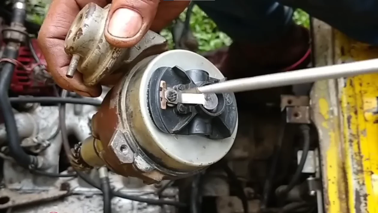
To time the distributor on a Suzuki Multicab F6A engine, set cylinder #1 to Top Dead Center on the compression stroke, align the flywheel mark before the letter “T” with the transmission mark, confirm the cylinder #1 cam lobes are facing upward and away from the lifters, then reinstall the distributor so the rotor points to the #1 terminal on the distributor cap.
The most common mistake is aligning the flywheel mark while the engine is on the wrong stroke. When that happens, the engine may crank but will not start.
Before You Start
Difficulty: Moderate
Estimated time: 30 to 60 minutes
Main task: Static distributor timing and distributor installation
Engine: Suzuki F6A 3-cylinder engine, commonly used in Suzuki Multicab models
Tools and parts you may need
- Socket wrench set
- Screwdrivers
- Flashlight or work light
- Clean rag
- Marker or masking tape for labeling wires
- Basic hand tools for removing the distributor cap or valve cover
- Replacement valve cover gasket if the old one is already brittle or leaking
- Timing light for final ignition timing adjustment after the engine starts
Safety warning: Work with the engine off. Keep your hands, tools, clothing, and wires away from belts, pulleys, and the fan. If you are not confident working around ignition parts or moving engine components, ask a mechanic to check your work before starting the engine.
What Distributor Timing Means on the F6A Engine
Distributor timing means the spark from the distributor is synchronized with the engine’s mechanical position.
On the Suzuki F6A engine, the distributor must fire cylinder #1 when cylinder #1 is at the correct TDC compression stroke. That is the moment when the piston is at the top, both valves are closed, and the spark plug is ready to ignite the air-fuel mixture.
The important part is this:
The flywheel mark can line up at TDC more than once during the engine cycle. You need the correct TDC, not just any TDC.
That is why you should check both the flywheel mark and the cam lobe position before seating the distributor.
Step 1: Find the Timing Mark on the Flywheel
Look at the flywheel area near the transmission casing.
You should see timing marks on the flywheel. In your reference, there is a letter “T” with a line before it. That line before the “T” is the mark you need to align with the mark or pointer on the transmission casing.
If your flywheel has several marks, do not panic. Some flywheels show multiple lines, especially if the flywheel has a different or hydraulic-style marking layout.
Use this rule:
Find the letter “T,” then use the line before the “T” as your TDC reference mark.
Rotate the engine slowly until that line is centered with the transmission mark.
Step 2: Confirm Cylinder #1 Is Really at TDC Compression
Do not rely on the flywheel mark alone.
A 4-stroke engine reaches TDC twice during its cycle:
| TDC position | What happens | Correct for distributor timing? |
|---|---|---|
| Compression stroke | Both valves are closed and the spark should fire | Yes |
| Exhaust stroke | Exhaust valve is open or closing | No |
To confirm cylinder #1 is at the correct TDC, remove the valve cover if needed and look at the camshaft lobes for cylinder #1.
On the F6A engine, cylinder #1 is the front cylinder, near the timing belt side.
At TDC compression, both cylinder #1 cam lobes should point upward and away from the valve lifters. A good visual shortcut is that the lobes look like a wide “V” or “bunny ears,” roughly around the 10 o’clock and 2 o’clock positions.
That position tells you both valves are closed.
If the lobes are pushing down on the valves, you are not on the compression stroke. Rotate the engine one full turn and check again.
Step 3: Identify the #1 Terminal on the Distributor Cap
Before installing the distributor, you need to know where the rotor should point.
On this F6A distributor setup, the #1 position is located to the left side of the vacuum advancer when you are looking at the distributor from the cap side.
The vacuum advancer is the round metal canister attached to the side of the distributor. Your visual reference is simple:
The #1 distributor terminal is the one just to the left of the vacuum advancer.
You can also confirm this using the high-tension wires.
The longest high-tension wire usually goes to cylinder #1 because cylinder #1 is farthest from the distributor. On the F6A layout described in your notes, the distributor sits toward the transmission or battery side, while cylinder #1 is farther away near the timing belt side.
That makes the longest plug wire a useful clue for finding the #1 cap terminal.
Step 4: Install the Distributor So the Rotor Points to #1
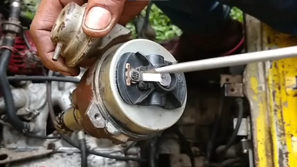
Now slide the distributor assembly back into the engine.
The rotor inside the distributor must point directly at the #1 terminal when the distributor is fully seated.
This part can be tricky because the distributor gear is helical. That means the rotor turns slightly as the gear meshes with the camshaft gear. It may look correct before you push it in, then move out of place as it drops.
Use this method:
- Hold the distributor near its installed position.
- Point the rotor slightly before the #1 terminal.
- Slide the distributor into the engine.
- Watch the rotor turn as the gear engages.
- Check where the rotor points after the distributor is fully seated.
- If it does not point to #1, lift the distributor slightly.
- Turn the rotor a small amount by hand.
- Drop the distributor back in again.
- Repeat until the rotor lands directly at the #1 position.
Do not force the distributor. It should sit flush when properly engaged.
If it sits high, the gear or shaft may not be fully engaged. Lift it slightly, rotate the rotor a little, and try again.
Step 5: Avoid the 180-Degree Timing Mistake
This is the mistake that wastes the most time.
You may line up the flywheel mark correctly and still have the engine on the wrong stroke. When that happens, the distributor may look installed correctly, but the spark fires when cylinder #1 is not ready to ignite.
The usual symptoms are:
- The engine cranks but does not start
- The engine tries to start but immediately dies
- There is popping through the intake
- There is backfire
- The timing feels correct, but nothing works
This happens because the crankshaft rotates twice for every one camshaft rotation. So the flywheel mark can line up while cylinder #1 is on the compression stroke or while it is on the exhaust stroke.
The fix is not to guess. Check the cam lobes.
If cylinder #1 cam lobes are not both facing up and away from the lifters, rotate the engine one full crankshaft turn, realign the flywheel mark, and check again.
Step 6: Reinstall the Distributor Cap
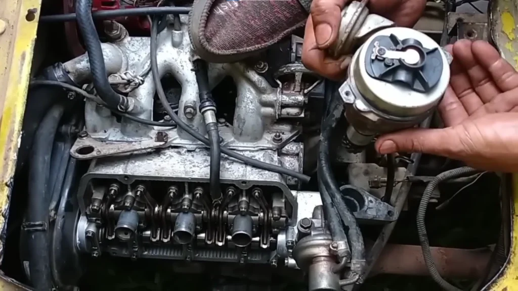
Once the distributor body is seated and the rotor is pointing at #1, reinstall the distributor cap.
Make sure the cap sits flat.
Do not tighten the cap while it is crooked. If the cap is not seated properly, the rotor can hit the internal terminals. That can damage the rotor, crack the cap, or cause a no-start problem.
Check these before moving on:
- The cap is seated evenly
- The clips or screws are secure
- The rotor has clearance inside the cap
- The distributor body is not loose
- No wire is trapped under the cap
Step 7: Connect the High-Tension Wires in the Correct Firing Order
The F6A firing order is 1-3-2.
Start at the #1 terminal you identified earlier. Then connect the plug wires in order around the cap.
Based on your note, count to the right around the cap.
Use this connection order:
| Distributor terminal order | Connects to cylinder |
|---|---|
| First terminal | Cylinder #1 |
| Second terminal | Cylinder #3 |
| Third terminal | Cylinder #2 |
Cylinder position matters here.
On the 3-cylinder F6A engine:
- Cylinder #1 is at the front, near the timing belt side
- Cylinder #2 is the middle cylinder
- Cylinder #3 is at the back, closer to the distributor side
If the wires are crossed, the engine may crank but not start. It may also pop, shake, misfire, or run very rough.
Step 8: Reinstall the Valve Cover and PCV Hose
If you removed the valve cover to inspect the cam lobes, reinstall it before starting the engine.
Check the gasket before tightening the cover. If the gasket is damaged, hardened, or pinched, it can leak oil.
Install the valve cover evenly. Do not overtighten the bolts.
Reconnect the PCV valve hose before starting the engine. A disconnected PCV hose can create a vacuum leak, rough idle, or poor running condition.
Final checklist before starting:
- Flywheel TDC mark aligned
- Cylinder #1 confirmed at TDC compression
- Distributor rotor pointing to #1
- Distributor fully seated
- Distributor cap installed flat
- High-tension wires connected in 1-3-2 order
- Valve cover installed
- PCV hose connected
- All tools removed from the engine bay
Step 9: Start the Engine and Check the Result
Once everything is installed, try starting the engine.
If the distributor was seated correctly and the plug wires are in the right order, the engine should start or at least show a clear sign that it wants to start.
After the engine starts, you may still need to adjust the distributor slightly for final ignition timing. Static timing gets the engine close enough to start. A timing light is the better tool for final adjustment.
Do not keep cranking the engine for too long if it does not start. Stop and recheck the basics.
Troubleshooting: Engine Cranks but Will Not Start After Distributor Installation
| Symptom | Likely cause | What to check |
|---|---|---|
| Cranks but does not start | Distributor installed 180 degrees out | Recheck cylinder #1 cam lobe position |
| Pops through intake | Spark firing on wrong stroke | Confirm TDC compression, not exhaust stroke |
| Backfires | Wrong plug wire order | Recheck 1-3-2 firing order |
| Starts but runs rough | Distributor slightly off or wires crossed | Check rotor position and wire routing |
| Distributor will not seat fully | Gear not meshing properly | Lift, rotate rotor slightly, and reseat |
| Oil leak after work | Valve cover gasket not seated | Reinstall gasket and cover evenly |
| High idle or rough idle | PCV hose disconnected | Reconnect the PCV hose |
How to Know the Distributor Is Installed Correctly
You are close when all of these are true:
- The flywheel mark before “T” lines up with the transmission mark
- Cylinder #1 cam lobes point up and away from the lifters
- The distributor rotor points to the #1 cap terminal
- The #1 terminal is identified near the vacuum advancer
- The high-tension wires follow the 1-3-2 firing order
- The distributor cap is seated flat
- The engine starts without backfiring
If one of those checks fails, do not move forward yet. Distributor timing problems are usually caused by one small mismatch.
Common Mistakes to Avoid
Using the flywheel mark without checking the camshaft
The flywheel mark only tells you the piston is at TDC. It does not always tell you the engine is on the compression stroke.
Always confirm the cam lobe position.
Forgetting that the rotor turns as the distributor goes in
Because the distributor gear is helical, the rotor moves as the distributor seats. Aim slightly before the final position so it lands on #1 after the gear engages.
Mixing up the high-tension wires
The F6A firing order is 1-3-2. If the wires are swapped, the timing may look correct but the engine still will not run properly.
Installing the cap unevenly
A tilted cap can cause contact inside the distributor. Seat the cap flat before tightening it.
Leaving the PCV hose disconnected
A loose or disconnected PCV hose can cause poor idle and make you think the distributor timing is still wrong.
When to Stop and Get Help
Stop and ask a mechanic to check the engine if:
- The engine backfires repeatedly
- The distributor does not seat flush
- The cap or rotor looks damaged
- The engine cranks unusually fast or unevenly
- You are not sure which cylinder is at TDC
- The engine still will not start after confirming the cam lobes, rotor position, and firing order
Repeated cranking with the wrong timing can cause more problems, especially if fuel builds up or the engine backfires.
Final Takeaway
Timing the distributor on a Suzuki Multicab F6A engine is mostly about lining up three things correctly:
- The flywheel TDC mark
- The cylinder #1 cam lobe position
- The distributor rotor pointing to the #1 cap terminal
Do not rely on the flywheel mark alone. Confirm cylinder #1 is on the compression stroke, seat the distributor carefully, then connect the spark plug wires in the 1-3-2 firing order.
That extra cam lobe check is what prevents the classic no-start problem where the engine cranks, pops, or backfires even though the timing mark looks correct.
FAQs
What is the correct firing order for the Suzuki F6A engine?
The firing order is 1-3-2.
Start from the #1 distributor cap terminal, then connect the next wires in the correct rotation around the cap.
How do I know cylinder #1 is at TDC compression?
Check the cam lobes for cylinder #1. Both lobes should face upward and away from the valve lifters. They should look like a wide “V” or “bunny ears.”
If one of the lobes is pressing a valve down, you are not on the compression stroke.
Why does the engine crank but not start after I align the marks?
The engine may be 180 degrees out of time. The flywheel mark can line up while cylinder #1 is on the exhaust stroke instead of the compression stroke.
Recheck the camshaft position, then reinstall the distributor with the rotor pointing to #1.
Where is the #1 position on the distributor?
In this setup, the #1 terminal is located to the left side of the vacuum advancer when looking at the distributor from the cap side.
You can also use the longest high-tension wire as a clue because cylinder #1 is usually farthest from the distributor.
Do I still need a timing light?
Yes, for final adjustment. The steps above help you seat the distributor correctly so the engine can start. A timing light is the proper tool for fine-tuning ignition timing after the engine is running.
